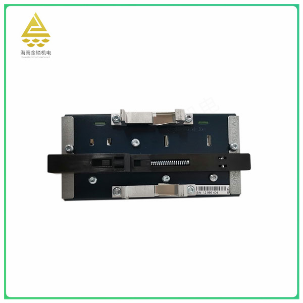
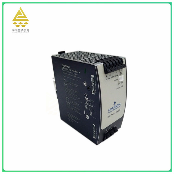
1X00781H01L is a power module widely used in industrial automation, power systems, communication equipment, robotics and other fields. It has output components such as high-power transistors and field effect tubes, which can drive both DC and AC loads. At the same time, it also has an output module such as a relay, which can provide normally open contacts for switching on and off external loads. In addition, it also has protective features, such as the RC circuit and varistor can eliminate the arc generated when the contact is broken to reduce the interference to the CPU.
In short, the 1X00781H01L is a high-performance, multi-functional, fully protected power module suitable for a variety of industrial automation application scenarios.
Digital input and output modules (I/O modules) are key components of every PLC (programmable logic controller). Specifically, they assume the control, communication and actuation functions of the PLC. But the numbers
I/O modules face increasing challenges. These challenges stem from the growing need for flexible usage and a fierce battle for market share occurring simultaneously in terms of system reliability.
Changing customer needs are also a factor. The IP protection and access restriction of the solution as well as its power consumption and system lifetime play a decisive role in the battle for customers. Safe ketoid change
Increasingly important, especially when it comes to controlling drives. In today's competitive market, long experience is essential, and features such as simplicity, low maintenance costs, and secure data access are plentiful
Dot.
One: PLC analog input module (analog input module), also known as A/D module, converts the continuous analog signal generated by the sensor detection in the field into a digital quantity that the PLC CPU can receive
Most are 12-bit binary numbers, and the more bits of the module, the higher the resolution.
Two: PLC analog output module. The analog output module is also known as D/A module, which converts the digital quantity sent by the PLC CPU to the analog output module into the analog quantity that the external device can receive (voltage or
Electric current). The digital signal received by the analog output module is generally a 12-bit binary number, and the more digital bits of the module, the higher the resolution. The digital quantity module is to detect the external switching quantity output
Incoming state.
Three: The digital input and output signal is the switching signal, 0 or 1, the analog quantity number, there are two kinds of voltage or current signals, generally the signal transmitted by the transmitter, such as the pressure transformer detection
Water pipe excitation, it will output an analog signal 4-20ma or 0-10V signal to the PLC, PLC for data processing, which is the difference between the digital input module and the analog input module.
In the input sampling phase, the PLC successively reads all input states and data by scanning and stores them in the corresponding cell in the /O image area. After the input sampling is complete, transfer to the user program execution
Row and output refresh phase. In both phases, even if the input state and data change, the state and data of the corresponding element in the I/O map area do not change. So if the input is a pulse message
The width of the pulse signal must be greater than one scan cycle to ensure that the input can be read in any case.


