The functions and characteristics of AAP3798102-00130 may vary depending on the specific application and context. In general, it may be an electronic device, component, or system that has some of the following common functions and features:
Features:
Input/output functions: AAP37998102-00130 may have input and output functions, capable of receiving and processing signals from other devices or systems, and output results to other devices or systems.
Computing and processing functions: The device may have computing and processing functions, which can calculate, analyze and process the input data to generate corresponding results or outputs.
Control functions: AAP37998102-00130 may have control functions that enable other equipment or systems to be controlled or adjusted to meet specific needs.
Features:
High efficiency: AAP37998102-00130 may be efficient, able to quickly process input data and generate corresponding results or outputs.
Stability: The device may be stable, able to work stably under different environmental conditions and maintain its performance and reliability.
Scalability: AAP37998102-00130 may be scalable, able to connect and integrate with other devices or systems to achieve more complex functions and operations.
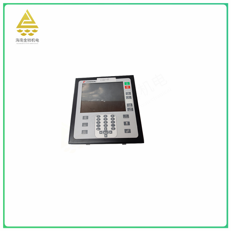
CAMERON AAP37998102-001 30 Universal Display compressor control module Install the patch board in the control housing with a common patch board or patch board and connect the shielded cable from the patch board
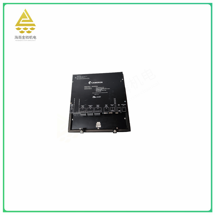
Connect to each input circuit on the block terminal. Y Connect the shield of each cable to the gold panel next to the patch panel. Do not connect shielding at the module end (Cut shielding at the cable module end)
Insulated with heat shrink tubes). Y Connect the field device to the terminal board with a shielded cable, grounding the shield only at the device end (cut off the shield at the terminal board end of the cable and insulate it with a heat shrink tube). In addition, the length of the exposed (shielded external) leads at the terminal board and device end should be reduced as much as possible. Direct method Y will shield the cable from the field
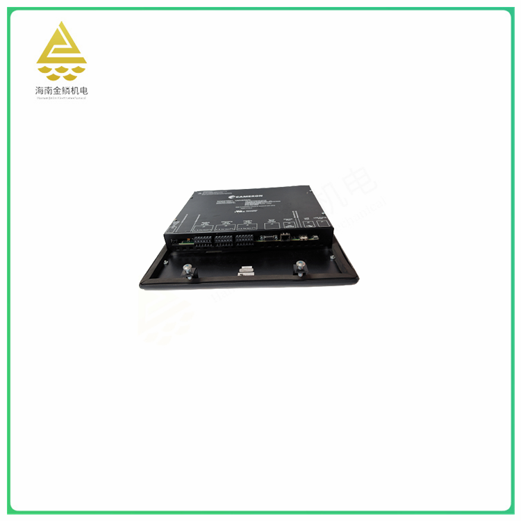
Devices (sensors, potentiometers, etc.) are connected directly to the module. Y Connect the conductor to the applicable screw on the module terminal board. Ground the shielding at the end of the field device so that a minimum number of conductors are exposed to noise. Do not connect the shield at the module end (cut the shield at the module end of the cable and insulate it with a heat shrink tube). CAMERON AAP3798102-001 30TBQC Not recommended for analog modules Due to cable shielding requirements, terminal board Quick Connection (TBQC)


