1 The external power supply connected to the relay can be DC or AC, which can directly drive 220v
Dc load, the external power supply of the transistor can only be connected to DC, not to the drive switch,
2. The switching frequency of the relay type is low, and the transistor can output high frequency signals such as servo systems
Transistor type PLC is used for the pulse output. In practical use according to needs
Select the appropriate PLC specifications.
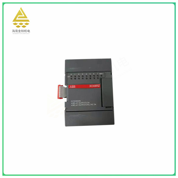
2PLC output terminal
Output terminal introduction
To illustrate with 40 terminals, 3 groups of input + 2 groups of output =5*40 terminals, where the input terminal has only one common terminal S/S, and the output has 5 common terminals. Y0 and Y1 use the com terminal separately, and Y2 and Y3 use the COM terminal separately
con2, Y4, 5, 6, 7 share com3, Y10, 11, 12, 13 share com4, Y14, 15, 16, 17 share com5.
3 Relay Wiring
The PLC output circuit of the relay type is shown below. Dc power supply and AC power supply can be used to drive the load, regardless of drain-source output.
Relay type PLC output loop
Common output controls in industrial control include motor, indicator light, alarm, electromagnetic valve, etc., one can be directly connected with PLC output terminal Y, and some need intermediate relays or contactors to connect.
The output line of these valves is two-wire system, one is connected to the live line, and the other is neutral line, which can be controlled directly by connecting the PLC output terminal with the power supply, generally adding a relay to protect the PLC
The relay contact is connected to the solenoid valve.
The output connects to the trunk
The output is connected to the contactor
4 transistor
The external power supply of a transistor type PLC must be DC, and there is a leaky connection, and the source connection is just the opposite of the input:
Transistor plc output
In addition to the external power supply is consistent with the load power supply, other outputs can not be directly connected to the load, its output and com end in the absence of output is semiconducting state, connected to the AC load normal conduction
Tong. This new guy. - Be careful. It is generally connected through the trunk load, this time the trunk is DC type, the coil must be mainly positive and negative.
For example, a PLC of the MT type controls the motor and indirectly controls the contactor through a 24v DC relay.
In general, the PLC output signal connection is simple, it can be understood that the PLC output is the two contacts of the coil and the com end, the two contacts are connected to both ends of the load, we just need to understand the PLC output
Type Wipe Type Specifies whether to drive through a trunk.


